Saturday, March 26, 2011

Part 5 - Router Base Assembly

The base consists of 4 x 1030 8020 extrusions purchased on ebay. The 8020 company sells overstock and other parts that don't meet the cosmetic standards for customer shipments. They have a great selection at affordable prices.

For the Crikey 2010, the base consists of:

2 x 10 Series 1030 extrusions 24" long for the Y axis $13
2 x 10 Series 1030 extrusions 26" long for the X Axis $15
32 x Economy T-Slot nuts  $5.25 for a pack of 25 ($0.21 each) so get multiple packs 
4 x Corner brackets - home made from an Aluminum 3x3 Angle 0.25" thick extrusion $22 for 48"

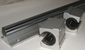
To create the corner brackets, the Aluminum angle was cut into 2" pieces and 1/4 holes drilled for 1/4-20 SHCS used to bolt the brackets to the 1030 extrusions using economy t-slot nuts. Slot spacing is exactly 1" with the first slot center exactly 1/2" from the edge. Here's an image showing the extrusions,corner brackets and the slides (and some other bits we will discuss later).
Base Components
Assembly is simply a case of sliding the T-Slot nuts into the slots and loosely engaging the screws. Keeping everything slightly loose will allow you to adjust things later on. You might find it easier to engage the t-slot nuts first and then slide the brackets into the slots. When the nuts lie loose in the slots, they fall at a slight angle to the screw making it tedious to get the screw to engage. 
Base Assembly - fully supported X and Y axis
To mount the slides, a couple of 1/2" x 1/8" x 26" aluminum bars were used. The bar will almost fit into the slots in the 1030 extrusions. To go from almost fit to actually fit,you will need to file or grind a roughly 45 degree chamfer on the back side until the bar slides into the slot on the extrusion with a small amount of freedom. You will need some freedom to ensure a small amount of adjustment is possible later on. 
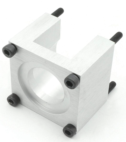
Long 26" Nut - you will need 2 of these - one for each slide
The grinding/filing takes time so you might want to consider a couple of beverages to keep motivation levels up. After you get the bar to fit nicely in the extrusion slot, you need to drill and tap the bars to form 26" long nuts. To do this, clamp the slide to the bar as a template and then drill holes that can be tapped using the appropriate screw size for your slides. In my case I used a 6-32 tap drill. You need to align the slide as accurately as you can with the aluminum bar as this will affect your alignment on the X axis. Preferably use a drill press to make neat perpendicular holes. Then set yourself down for the tapping marathon. Each hole needs to be tapped. This is super tedious work. After you are done, cut the nut into roughly 3 inch sections. I tried to use the nut as one long piece but it is difficult to adjust once the slide is screwed to it. Cutting it up made adjustment much easier. The good thing is you now have the experience needed to do the same thing all over again for the Y Axis.... but that comes later.
If you want to see an example of what you can do with the router when you have it finally assembled and working, here's a link to my other blog showing a part created for a motorcycle:

http://midnightcustoms.blogspot.com/2011/03/part-8-regulator-and-cnc-switch-mount.html

And that's all for now. I'll transcribe more notes as I find time.

Part 4 - Linear Motion

Linear Motion


We have figured out the components we need to mount a motor, so now it's time to decide on the other critical parts of the linear motion system. You have more choices here than days in a month. For the Crikey 2010 (yes, that's it's name even though it was built in 2009) 12mm linear slides where used. There are other interesting choices available. For example:
V-Groove system from Bishops-Wisecarver or the U-Groove Guide Bearings, they are available from VXB Bearings.

12 U Groove Guide Bearings:vxb:Ball Bearing
The most common linear motion systems for home built CNC systems use linear shafting with linear bearings. Linear shafting flexes under load which becomes more problematic the longer the shaft becomes. Purists will have you believe that this is a poor choice. Depending on your overall length and shaft diameter, this type of motion system may be suitable for your application. There are many variations that use open linear bearings which allow you to provide extra support underneath the linear shaft. With the extra support, flexing can be significantly reduced. A set of 20mm x 30" hardened steel shafts (qty 2) with a set of linear bearings (qty 4) will run in the region of $80. Now add in the shaft supports and bearing blocks and you very quickly approach $120 - and that's just for one axis. Obviously as the shafting diameter is reduced, the cost reduces but so does the cutting load the router is able to withstand without flexing too much.

 16mm Open Linear Motion Bearing/Bushing:vxb:Ball Bearing20mm Linear Guideway System 55inch Long Rail with 2 Built-in Trucks

www.vxb.com has 44" (and longer) linear guideway systems similar to the above. For the 16mm shafting, a 44" length will run you around $87, with the trucks coming in at around $27 each. You will need to run your own cost benefits analysis to see what works for you. Each axis will require 2 linear guideways and 2 trucks. Money adds up fast when you play with linear motion systems.

I found an ebay vendor (Toolssales) who packages a set of parts as kits at good prices. The parts ship from Hong Kong so you'll probably need to be patient. I have not bought from this vendor so do your homework regarding ebay feedback reviews. 


Okay, back to the Crikey 2010. For this project I used linear slides supported by the 8020 extrusions for rigidity. Slides are hit and miss on www.ebay.com, but that is the only place for occasionally affordable slides. 


What I recommend for this design are 15mm linear slides. New slides are very precise and can match the prices of linear shafting. The slides I'm using have a 12mm rail and are 26" and 21"long made by IKO. I would have preferred 15mm slides but you take what you can get and the 12mm slides have held up very well over the 2 years of operation cutting aluminum and wood.


Automation Overstock has very good prices on linear slides. The manufacturer is HIWIN.  : http://www.automation-overstock.com/

For a single axis, you need 4 bearing blocks and 2 rails. Using the 15mm parts from Automation Overstock, you will end up at around $160 per axis or $480 for the X,Y and Z axis. Roughly the same as large diameter linear shafting and in my opinion a better choice. If you scale up to the 20mm system, you will end up at around $600 for all 3 axis. I'll say it again. Motion systems cost money. Precision components don't come cheap. 

Bearing blocks and rail
That's all for now. With the slides selected and on-hand, it is time to move on to the base frame components and assembly. 


Wednesday, March 23, 2011

Part 3 - More Parts...

Shaft Coupling


You will need to connect the motor to the leadscrew with a shaft coupling. The shaft coupling allows for a small amount of angular and linear misalignment of the motor shaft and the lead screw.  The coupling will also manage the different diameter of the leadscrew (1/2") and the motor output shaft (1/4").
Lovejoy couplers are cost effective. Depending on choice of spider material backlash on the couplings will increase over time due to deformation of the spider. There are a variety of elastomers to choose from - Urethane or Hytrel would be a better choice than the low cost Buna-N Rubber. When you buy the lovejoy couplings you have to buy 2 couplings plus the spider to complete the assembly. Since most stepper motors have a 1/4" shaft and we need to couple to the 1/2" leadscrew, we will select a 1/4" and 1/2" coupling with a urethane spider. The spider also dampens the vibrations from the stepper motor for quieter and smoother operation. Urethane spiders do not dampen vibration as well as the rubber spider, but can handle 1.5 times as much torque.


To order from ENCO  www.use-enco.com , the following part numbers are needed. You will need to order 3 sets, one set for each axis. A set consists of a 1/2" hub, a 1/4" hub and a spider.

Model #990-4046    Hub  1/2" Inner Bore   1.08" OD 1.72" Length
Model #990-4044   Hub  1/4" Inner Bore   1.08" OD  1.72" Length


Model #619-3475   Urethane Spider  $5.95 ea


Thrust Bearings 
The motors that drive each axis are not designed for axial loads. You need to decouple the thrust of the leadscrew from the motor by using a thrust bearing. This is important. Leaving out the thrust bearing will result in damage to the motor over time. Thrust bearings are cheap, motors not so. Use them. ENCO and McMaster have good prices on needle type thrust bearings. These are preferable to the low-cost ball style thrust bearings as the thrust is distributed over a larger area. The ultra low cost ball style thrust bearings are better than not having a thrust bearing at all though.
Needle style thrust bearings are more suited for heavy duty low friction work.

border=0
Needle-Roller Thrust Bearings (image from McMaster.com )


No matter where you buy your thrust bearings, for a complete bearing you'll need one cage assembly and two washers.

P/N 5909K31 Needel Roller Bearing Cage Assy $2.65 ea
P/N 5909K44 0.032" thick Steel Washer  $0.90 ea 

P/N  #891-4795 Needle Roller Bearing Cage Assy $2.95 ea
P/N  #891-4802 0.032" thick steel washer $0.95 ea


Tuesday, March 22, 2011

Part 2 - Parts...

It's debatable whether building your own CNC router is a cost effective way of getting a CNC machine into your garage. But what you learn in the process has high value and you can't quite put a price on that. There is a reason aluminum and steel constructed machines from reputable manufacturers are expensive - they have a lot of engineering behind them and they are not high volume products so it's difficult to get economies of scale for production. NOTE: Update 2019: Since this post was written in 2011, the landscape has changed considerably and a number of "affordable" machines based on aluminum extrusions are available for direct purchase. The CNC hobby machine market has exploded with offerings from companies like Carbide3D https://carbide3d.com/shapeoko/,
Inventables X-Carve https://www.inventables.com/technologies/x-carve,

At the Prosumer end of extruded aluminum machines, CNC Router Parts makes some excellent machines if you have the money  http://www.cncrouterparts.com/

At the lowest cost end are some low cost imports that some have had great success with and may help you get a basic appreciation of CNC machining before you go and spend more money on a larger more capable machine.
https://www.amazon.com/s?k=cnc+3018

Anyway, lets get to the parts since I'm assuming your wallet is now ready for the great big sucking sound that is associated with building your own CNC Router:

Spindle Router
Hitachi M12VC 2-1/4-Horsepower Variable Speed Router
Variable speed is useful for efficiently cutting different materials and controlling noise levels (yes, I do have neighbors).
This router is currently available on http://www.amazon.com/ for $103


http://www.k2cnc.com/ has a ready made holder for this router which will save you some serious fabrication time especially if you are using hand tools to cut the parts. 

  
Leadscrew
This design uses 1/2-10 ACME thread. You can get really low prices for leadscrews from ENCO but the threads are very rough and will destroy your nuts in no time at all. I bought some that ended up in the recycling pile. Nothing against ENCO just pointing out that parts for an automated CNC machine need a better finish than parts made for general industrial use. 


McMaster and MSC have leadscrews with polished threads. This is a better choice for CNC. There are a number of arguments on the web regarding leadscrew accuracy. Practically, unless you are concerned with 0.001 accuracy over a 12 foot span, the ACME screws from McMaster and MSC are perfect for home construction. Most parts are much smaller than 12" long so obsessing over ACME specs is a waste of time. I ordered 4 of these:


Leadscrew Nuts
You have many choices here. The best choice is to use an anti-backlash nut. these are a bit pricey but I recommend them if your wallet can handle it. For this build, I made my own nuts from Delrin. They are not anti-backlash but I figured that as soon as the backlash starts affecting the accuracy, I'll make new ones. I found a sheet of 3/4" black delrin on ebay for $7 so the nuts cost roughly $2.33 each. 


The nut is bolted to the frame using 1/4-20 SHCS. Threading requires an ACME tap. Taps are available from MSC (http://www.mscdirect.com/) but they are expensive. 

MSC ACME Tap


If you have the patience you can make your own from an offcut of the 1/2-10 ACME threaded rod. I got the idea from http://www.embeddedtronics.com/acmetap.html

Here's the tap I made. Use a dremel tool or grinder to reduce the diameter of the start of the screw and then mill 3 slots up the shaft roughly 120 degrees apart. When using the tap, all the removed material needs somewhere to go so it ends up in the slots. Make then as deep as you dare. Drill a 1/4" hole near the top into which you can slide a 1/4" steel rod to use as a handle. The ACME nut on the top was used to jam the rod in place. ACME nuts don't jam very well so add locktite.

Homemade ACME tap

Motors
Stepper motors are cheaper than servos and the most common motor used for DIY and lower cost commercial offerings. They are run in open loop mode to simplify the design. Encoder feedback adds cost and complexity. As long as your steppers have high enough torque to overcome cutting loads without slipping, stepper motor systems will serve you well. Stepper torque reduces with increasing speed so you will occasionally have to throttle back to get through harder materials. 
http://www.pdjinc.com/parts.html has 439 oz-in NEMA 23 Steppers listed at $45 each. That is a great deal.
Automation Direct also has good deals on steppers. A listing of what they have available can be seen at
My recommendation should you choose the Automation Direct motors would be the 276 oz-in, 200 steps/revolution Nema 23 motor.

I found NEMA 23 motors on ebay. My recommendation is to stick with NEMA 23 at 276 oz-in or higher torque motors. 

NEMA 23 Stepper Motor


Motor Mounts
Once you have found your steppers, they need to be mounted. I would tend to go for aluminum mounts for rigidity.

Considering how much time and effort is involved in manufacturing your own (and the additional time and materials cost for correcting the inevitable mistakes) buying these makes some sense. There are a number of other ebay auctions all offering different flavors of NEMA 23 mounts. For example, these nice looking mounts were available from https://www.amazon.com/s?k=nema+23+mount&ref=nb_sb_noss_2


Not having much sense I went ahead and made my own using the Micro Mill. The parts were first modeled in 3D CAD to make sure everything would fit. Each axis (a router has 3 - x axis from left to right, Y axis from front to back, and Z axis for up and down) is basically a replica of this assembly. Each component of the motor assembly will be discussed in detail later on.

Key components for each motion axis assembly

Once the modelling was done, the parts were machined, slowly and carefully with a shop-vac providing a cooling stream of air. 

Machining the motor mounts


Once the motor mounts were machined and deburred, holes are drilled for 10-24 taps on one end and 10-24 clearance holes on the other end.
Tapping the holes on one end


To be continued......

Part 1 - CNC Custom Router Intro

8020 CNC Router Build

The goal is to build a CNC router from 8020 aluminum extrusions. There are a number of impressive designs made entirely from MDF, UHMW, plywood and other low cost materials. These have all been a source of inspiration in some way or another. This is not my first CNC machine. I have previously converted a Harbor Freight Micro Mill to CNC, and designed and built a tiny router from 3/8" acrylic (nanoCNC). Both of these machines are too small for some of the projects I want to tackle. I have no intention of restricting the tools needed for building this router to commonly available workshop tools. This is not an Instructable - just a loose guide to building your own and detailing the essential elements of construction. Ultimately the picture below shows where we will end up, but that is jumping ahead a lot. If you can figure out what you need to do looking at the picture, then you can skip the rest of the blog! If you need more detail, read on....

The completed CNC Router

Goal

Size
Cutting area in the region of 18 inches X-Axis, 20 inches Y-Axis with about 4 inches of Z-axis travel. The size limitation is physical space in an already crowded garage, the added expense of going larger (extra support to keep things rigid over a longer span, longer lead screws or rack and pinion drive, more torque required from the stepper motors etc. you get the idea) and the additional technical complexities of a large router.

Material Cutting Capability 
Must be capable of cutting hardwoods, MDF, plastics, aluminum and other non-ferrous metals. Aluminum requires a rigid machine. This is one of the reasons for using 8020 construction as apposed to MDF or other wood/plastic based construction materials.

Accuracy
It would be nice to be able to achieve 0.005" accuracy with repeatability of 0.002". Just seems like a decent goal.

Rapid Speeds
40 IPM should be achievable. Not going to break any speed records but suitable for my needs.

-